Your location:

/ Valve products / ball valve / Eccentric Semi-ball Valve / PQ640Y Pneumatic Eccentric Semi-ball Valve
全国销售热线:0577-67378222

Product classification of Kaiweixi

KAI WEI XI CHAN PIN FEN LEI
  • PQ640Y Pneumatic Eccentric Semi-ball Valve

  • More Eccentric Semi-ball Valve>>

  • More ball valve>>

  • More valve>>

Contact Us
  • Phone:+86(577)67307899
  • Mobile:+86 13325981263
  • Fax:+86(577)67387099
  • Email:shubai@kaiweixi.group
  • Address:
  • Website:https://www.kaiweixi.group
Other valve products you may need
  • DYP940F Electric Top-entry Semi-ball Valve
  • PQ340H Side-entry Semi-ball Valve
  • PQ940F Electric Eccentric Semi-ball Valve
  • PQ340Y Worm Gear Operated Eccentric Semi-ball Valve
  • PQ40F Manual Eccentric Semi-ball Valve
PQ640Y Pneumatic Eccentric Semi-ball Valve

PQ640Y Pneumatic Eccentric Semi-ball Valve

  • Model:PQ640Y
  • Specification:DN50-DN2000
  • Temperature:≤80℃
  • Medium: Water
  • Pressure:PN10,PN16
  • Connection method:flange
  • Driving method: pneumatic
  • Material:cast iron, ductile iron, stainless steel
x

Add QR code to serve you!

x

Add QR code to serve you!

x

Add QR code to serve you!

x
PQ640Y Pneumatic Eccentric Semi-ball ValveOverview

The PQ640Y pneumatic eccentric Segment Ball valve is a valve actuated by a pneumatic actuator. It utilizes compressed air to drive the actuator mechanism, combined with an eccentric crankshaft design on the valve stem, enabling rapid and stable valve flap operation and regulation. Featuring a metal hard-seal structure, this valve offers excellent wear resistance, high-temperature tolerance, and automated control capabilities. Widely applicable in demanding industrial environments such as petroleum, chemical, metallurgy, and environmental protection sectors where frequent opening/closing or remote automated control is required, it serves as a reliable device for efficient pipeline fluid cutoff and process automation.

PQ640Y Pneumatic Eccentric Semi-ball Valve Product Diagram

PQ640Y Pneumatic Eccentric Semi-ball ValveCharacteristic

1. Pneumatic actuators deliver rapid and reliable performance: Featuring piston or rack-and-pinion mechanisms, they provide swift response with minimal on/off time, support remote and automated control, and can be integrated with positioners for precise proportional regulation.

2. Excentric metal hard seal: The valve disc and seat are made of hard alloy or super-hard material through overlay welding, combined with the motion of eccentric crankshaft to achieve frictionless opening/closing and zero leakage sealing, with excellent erosion resistance, high-temperature and high-pressure resistance.

3. Bidirectional sealing and long service life: The valve is designed for bidirectional sealing, with minimal wear on the sealing pair during operation, ensuring extended service life. It is particularly suitable for harsh media containing particles or slurries.

4. Low flow resistance and anti-clogging: When fully open, the valve body channel is nearly identical to the pipeline inner diameter, ensuring strong flow capacity, minimal pressure loss, and preventing medium deposition or blockage.

5. Compact and easy-to-integrate design: The integrated actuator-valve assembly ensures convenient installation, supports multiple control signals and accessory expansion, facilitates integration into automation systems, and simplifies maintenance.

PQ640Y Pneumatic Eccentric Semi-ball Valvestructure principle

PQ640Y Pneumatic Eccentric Semi-ball Valve Structure Diagram

List of Component Names and Materials

Component NameCommon materials
body、bonnetWCB304(CF8)316(CF8M)316L(CF3M)
ball2Cr13+nitriding304316316L
stem2Cr13304316316L
seat sealing ringPTFE、 Carbon fiber+PTFE, para polystyrene
packingV-type PTFE、V Type PTFE、flexible graphite


PQ640Y Pneumatic Eccentric Semi-ball Valvetechnology parameter


Performance Specification Sheet

Performance Specification Sheet
Nominal Pressure1.01.6MPa
Strength test pressure1.52.4
Sealing test pressure1.11.76
Applicable Temperature≤80℃

Standard requirements for external dimensions

1. The structural length of the valve shall comply with the standard of GB/T12221

2. Connecting flanges according to GB/T17241.6 standard


PQ640Y Pneumatic Eccentric Semi-ball Valvestandard size

Outline dimension table

PN(Mpo)/Nominal pressureDN/Nominal diameter (mm)Size (mm)
mminL flangeDD1D2D6bfZ-φd
PQ340HYF –1.0CPR40–16514511085–1634–18
50–178160125100–1634–18
65–190180145120–1834–18
80–203195160135–2034–18
100–229215180155–2038–18
125–254245210185–2238–18
150–267280240210–2438–23
200–292335295265–2438–23
250–330390350320–26312–23
300–356440400368–26412–23
350–400500460428–28416–23
400–405565515482–28416–25
450–480615565532–30420–25
500–533670620585–30420–25
600–680780725685–34520–30
700–740895840800–38524–30
800–8501010950905–42524–34
900–1100111510501005–38528–33
1000–1200123011601080–38528–36
1200–1300145513801292–44528–39

Nominal pressureNominal diameterSize
mminLDD1D2D6bfZ-φd
PQ340HYF-1.6CPR40-16514511085-1634-18
50-178160125100-1634-18
65-190180145120-1834-18
80-203195160135-2038-18
100-229215180155-2038-18
125-254245210185-2238-18
150-267280240210-2438-23
200-292335295265-26312-23
250-330405355320-30312-25
300-356460410375-30412-25
350-400520470435-34416-25
400-406580525485-36416-30
450-480640585545-40420-30
500-533705650608-44420-34
600-680840770718-48520-41
700-740910840788-50524-41
800-8501020950898-52524-41
900-11001120/11251050998-44528-39
1000-1200125511701110-46528-42
1200-1300148513901325-52532-48

Due to the rapid R&D iteration speed of valve products from China Kaivex Valve Group Co., Ltd., the above technical parameters and specification documents, including product overview, features, parts materials, outline dimension charts, CAD drawings, and product instruction manuals, are for your reference only. For actual applications, please contact our valve sales engineers to obtain the support you need for free. Thank you!

Articles related to technology research and development
  • Wafer-type ball valve patented

       The utility model provides a wafer-type float valve, which includes a valve body and a driving mechanism. The valve body is provided with a through medium channel in the axial direction, and is tubular in shape. It also includes a butterfly plate that fits and seals with the inner wall of the medium channel. The driving mechanism comprises a valve shaft that passes through the valve body and is connected to the butterfly plate, a valve rod connected to the outer end of the valve shaft in the radial direction, and a float ball connected to the valve rod. The valve rod is provided with a limit bolt that is threadedly connected to the valve body in the swinging direction. The butterfly plate can rotate relative to the valve body. The front end of the valve body at the inlet of the medium channel is provided with a filter screen, which is hollow and hemispherical in shape. The end face of the valve body opposite the filter screen is provided with an annular groove, and the open end of the filter screen is provided with a raised edge that is embedded in the annular groove. The utility model can filter the medium, is simple to install, time-saving, labor-saving, small in size, widely applicable, and can reduce the impact force of the medium on the butterfly plate.
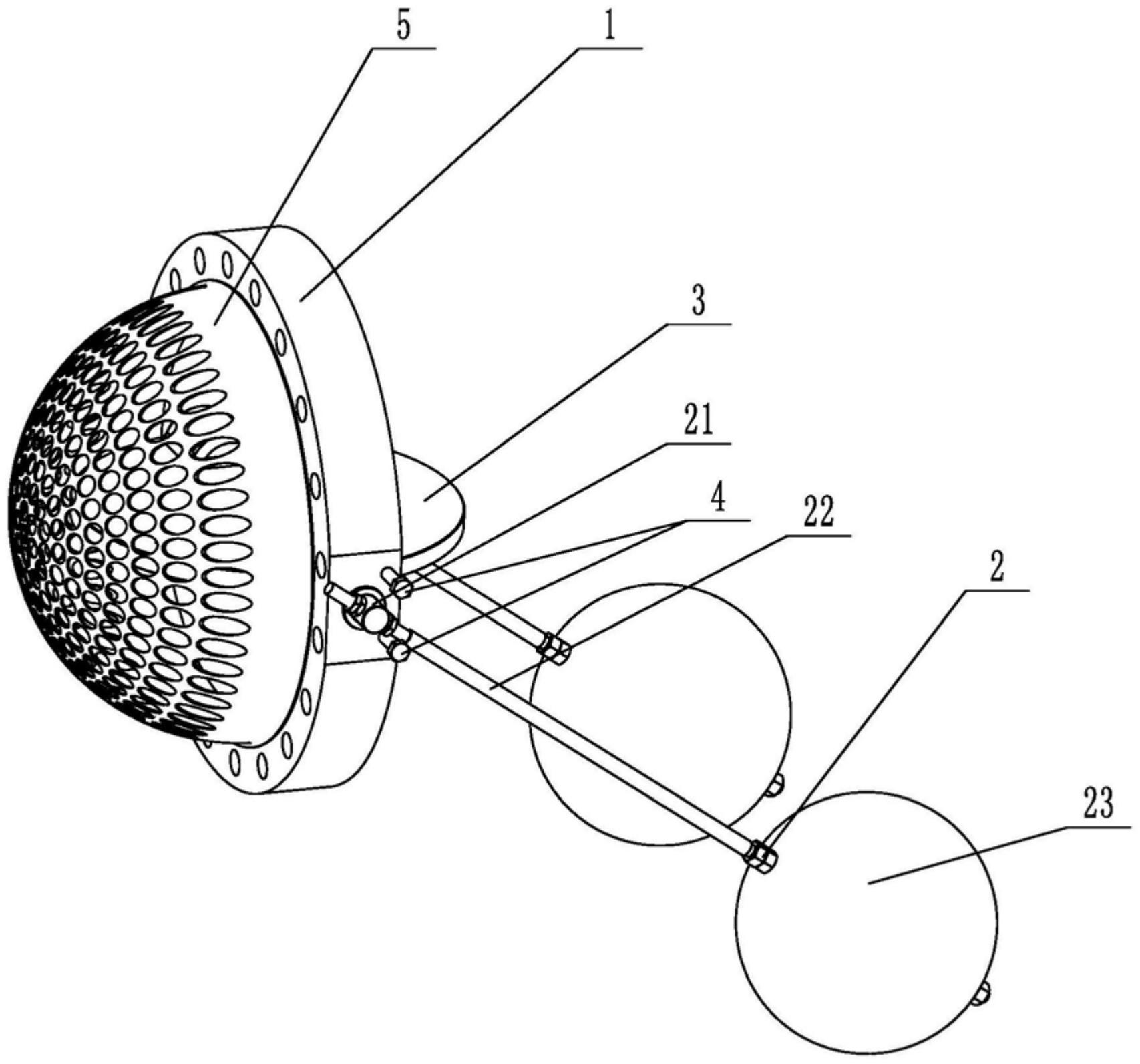
    1. A double-clip type float valve, comprising a valve body and a driving mechanism. The valve body is provided with a through medium channel in the axial direction. It is characterized in that the valve body is tubular and further comprises a butterfly plate that fits and seals with the inner wall of the medium channel. The driving mechanism comprises a valve shaft passing through the valve body and connected to the butterfly plate, a valve rod connected to the outer end of the valve shaft in the radial direction, and a float connected to the valve rod. The valve rod is provided with a limit bolt threadedly connected to the valve body in the swinging direction. The butterfly plate is rotatable relative to the valve body. The front end of the valve body located at the inlet of the medium channel is provided with a filter screen. The filter screen is hollow and hemispherical. The end surface of the valve body opposite the filter screen is provided with an annular groove. The open end of the filter screen is provided with a convex edge embedded in the annular groove.

    2. A wafer-type float valve according to claim 1, characterized in that the valve rod penetrates one end of the valve shaft located outside the valve body, and is threadedly engaged with the valve rod through a nut to clamp the valve shaft and achieve positioning of the valve rod.

    3. A wafer-type ball valve according to claim 2, characterized in that a step is provided at the position on the valve shaft connected to the valve body, a groove is provided at the position on the outer circumferential wall of the valve body corresponding to the step, and a gland is sleeved on the valve shaft, which is threadably connected to the groove and abuts against the step.

    4. A wafer-type ball valve according to claim 3, characterized in that a sealing groove is provided on the side of the groove facing the butterfly plate, and a sealing ring sleeved on the valve shaft is arranged in the sealing groove.

    5. A wafer-type ball valve according to claim 1, characterized in that an inner groove is provided on the side wall within the annular groove, and an elastic snap ring, which is used to press the convex edge and is compatible with the inner groove, is provided within the annular groove.

    6. A wafer-type ball valve according to claim 5, characterized in that the bottom of the convex edge is provided with a plurality of protrusions arranged around the center of the filter screen, and the annular groove is provided with a limiting groove adapted to the protrusions.

    7. A wafer-type float valve according to claim 6, characterized in that the protrusion is hemispherical. 8. A wafer-type float valve according to claim 7, characterized in that a clamping groove is provided at the junction of the protrusion and the protruding edge, and a clamping block adapted to the clamping groove is provided at the opening of the limiting groove.